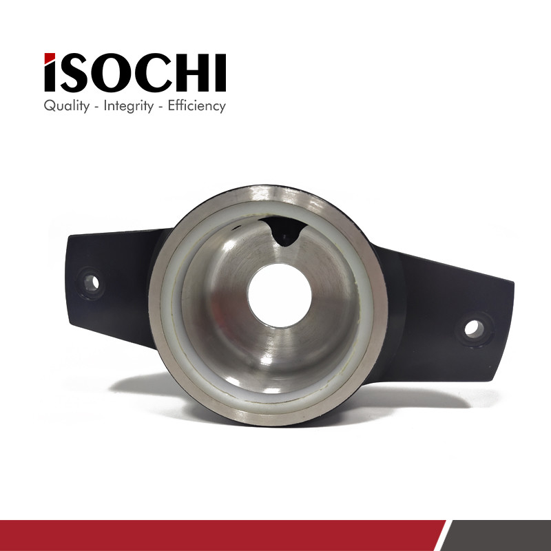
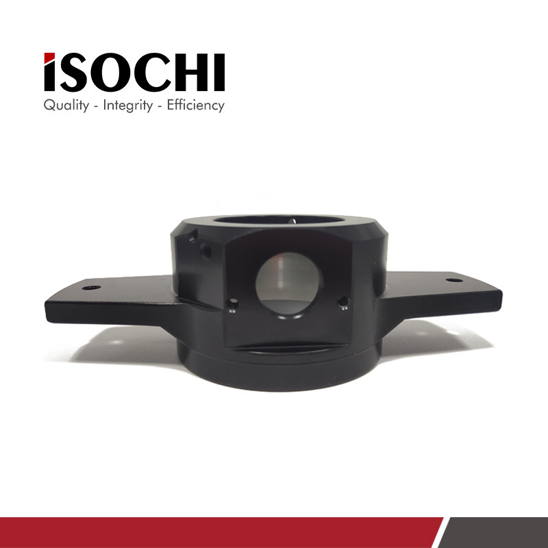
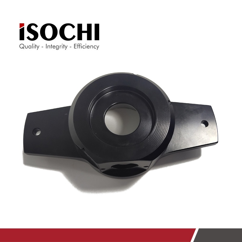
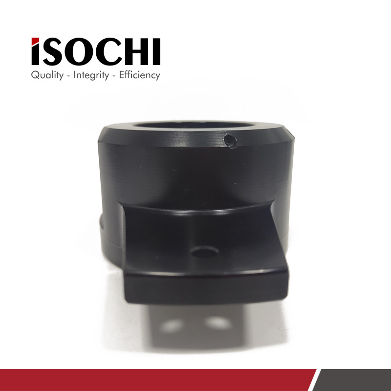
High Precision PCB Pressure Foot Cup For AEMG Routing Machine Customize Availale
Discribtion:
Pressure Foot is the irreplaceable part on PCB molding machine. It is placed on pneumatic rod to link with brush
parts for cleaning the PCBA that prevents PCBA from been corroded and oxdized. This new type pressure foot is
ued on the AEMG routing machine.
Specifications:
| Brand Name: | ISOCHI |
| Material: | Aluminum |
| Lead Time: | 3 Days After Payment |
| Place Of Origin: | Jiangsu,China |
| Customized: | Available |
| Application: | CNC PCB Anderson/AENG Routing Machine |

Pressure foot assembly:
In the case of the correct selection of the cover plate and the backing plate, the pressure foot assembly consisting of the synchronous cylinder, the chip suction cover and the pressure foot is a key factor affecting the quality of the drilling. In the past when drilling holes with a diameter of 0.5mm or more, under the condition that the CPK (Process Capability Index) ≥ 1.33 on the reverse side of the floor and the hole wall roughness ≤ 25.4μm were used, a fixed chip suction cover and a single-hole pressure foot were usually used. As the drilling hole diameter of printed circuit boards is gradually reduced (currently mainly concentrated at φ0.3mm, most of φ0.1 ~ 0.2mm), the precision of the pressure foot assembly of traditional chip suction hood and single-hole pressure foot configuration in the drilling accuracy And drilling quality are somewhat inadequate, which affects machining accuracy. To this end, a switching foot assembly is designed. The inner diameter of φ8.5mm is responsible for drilling large holes, and the inner diameter of φ2.5mm is responsible for drilling small holes. The open area between the inner diameter of the pressure foot and the drill is more obvious than that under a single pressure foot. Reduced, PCB workpiece system is pressed more firmly and leveled. The most common presser foot switch on the market. It is mainly divided into two design concepts. One design concept is the design concept of the integration of the large and small pressure feet of the German Schmoll company. The large and small pressure feet of this structure are on the same flat sliding plate, as shown in Figure 2. The air cylinder is directly connected to the slide plate drive, or the steel wire rope is used to drive the air cylinder. The advantage is that the structure is relatively simple, the machining is easier to implement, and the process is easier to maintain. The disadvantage is that the pressure foot is in the small hole position, and only three-quarters of the pressure foot around the drill bit fits the workpiece tightly. A quarter of the pressure foot must leave a channel for the pressure foot size hole switch, and can only rely on the farther positionable pressure foot to press the workpiece system. Another design concept is the design concept of large and small holes separated by Hitachi, Japan, as shown in Figure 3. The large and small pressure feet of this structure are fixed in an arc-shaped pressure foot seat, so that the pressure feet can switch between large and small holes. The advantage is that the pressure foot is in the small hole position, and the periphery of the drill bit can be tightly fitted; the disadvantage is that the structure is complicated, the arc-shaped mating surface is difficult to process, and it is difficult to maintain during use. The figure illustrates the effect of the size of the presser foot and the negative vacuum pressure on the aluminum sheet during the drilling process. It can be clearly seen from the figure that the excessively large presser foot is uniform during drilling due to the effect of negative vacuum pressure. The aluminum sheet is sucked up, causing protrusions, and it is easy to cause large deviations in the drilling. The use of independent small presser feet can reduce the adsorption of the aluminum sheet by the vacuum pressure due to the concentrated distribution of the pressure range, and improve the drilling accuracy. . The key point of the dust extraction hood design is efficient dust extraction efficiency. The results of the CFD analysis of COMSOL are shown in Figure 4. The flow lines in the dust extraction hood are mainly tangent to the outer diameter of the spiral, so as to maximize the suction cross-sectional area. The vertical position of the outlet should be as close to the bottom of the suction hood as possible, which is more conducive to the "washing hood" circulation flow, and at the same time to avoid affecting the inflow of the gap in the outer ring of the spindle and being blocked by the vertical moving spindle. By using the smallest possible gap between the dust suction hood and the main shaft, the tangent of the center line of the outlet and the outer diameter of the dust spiral line, and the lightest weight design possible, the dust suction hood can be efficiently vacuumed while taking care to prevent electrostatic interference.


Form and material of pressure foot:
The main function of the pressure foot is to compact the workpiece system. Through its slotted ventilation structure, it provides air supplement for the vacuum system, forms a better convection system, and has a larger buffer effect. Different brands of mechanical drilling design manufacturers based on different considerations, the material of the pressure foot is metal materials and non-metal materials. Metal materials are mainly stainless steel (usually SUS304) and brass materials (C3604BD, equivalent to HPb59-1). Non-metal materials are mainly PA66, PA6, POM and PU. The main considerations for the use of metal materials are relatively high hardness, wear resistance, and long service life (normally 8-10 months can be used); the disadvantage is that the buffer effect is not obvious, and it has not stabilized for a long time. The use of industrial rubber materials (PU, PA6 PA66) mainly considers good vibration absorption characteristics. For the impact process, it can achieve a significant vibration absorption effect, and the amplitude can be reduced in a short time. The disadvantage is that the hardness is relatively low and it is not resistant to wear. Life is short, usually around a week. Using ABAQUS software simulation, adjust the presser foot material, analyze with 100N presser foot force and 10kpa vacuum void, and analyze the use of rigid presser foot and PU presser foot. As shown in Figure 5, the upper and lower curves respectively indicate the numerical displacement curve of the "drill point" under the steel presser foot and the PU presser foot. It can be seen that the presser foot impacts with the presser foot force and oscillates, and the oscillation attenuates regularly within 0.06S; however, the PU presser foot has a significant vibration absorption effect. After the oscillation is initiated, the "drill down point" quickly stabilizes. Stability is reached at about 0.001S. Based on the good vibration absorption performance of industrial rubber, most drilling machine manufacturers currently use industrial rubber pressure feet.

More pictures:

 Your message must be between 20-3,000 characters!
 Please check your E-mail!
  Your message must be between 20-3,000 characters!
 Please check your E-mail!

